
Nowadays, a day without electricity cannot be imagined. In our daily life, the use of electricity is constantly increasing. I have to be very careful in the use and repair of electricity. Due to ignorance and unconsciousness fatal accidents can take away precious lives. Therefore, the importance of following government regulations and using proper safety equipment while working on electrical lines is immense.
Symbols used in electrical circuits:
variety of symbols are used to briefly and easily understand the components of an electrical circuit. Electrical fittings – all special symbols used to show the position of electrical fittings and equipment in drawings or drawings are considered electrical circuit symbols. Those who are engaged in the installation and repair of electrical equipment must have an understanding of these symbols.
List of symbols used in electrical circuits:-
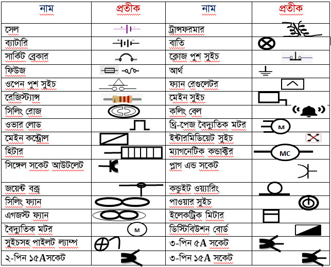
Requirements for use of electrical circuit symbols:
Drawing is the language of engineers. “Therefore, consequently, all electrical installation activities are carried out by looking at the drawing or design.” Various symbols are used to represent electrical fittings-fixtures and equipment in drawings or designs which are seen by the engineer or technician as they perform the installation work. So it can be said that the necessity of using symbols for electrical circuits is immense.
Examples of using electrical circuit symbols:
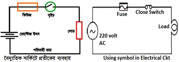
There are numerous symbols used in electrical circuits. Be aware of the use of symbols in circuit drawings. Some equipment has polarity. “As a result, therefore, there is a possibility of damaging the device if, for example, positive is placed instead of negative. Furthermore, below are some electrical equipment symbols shown in circuit drawing.”
Electric current and voltage:
Current and voltage are two important quantities of electricity. The word current means flow. “The meaning of electric current is, in fact, the flow of electricity or electric charge. Specifically, the amount of charge that flows through a unit area of a conductor in a single time is called electric current. Therefore, electric current, often denoted as I, is expressed by (I); moreover, its unit is the ampere.”
Formula , Current = Charge / Time,
I=Q/t ampere
“The pressure or force that is applied to flow electrons or charge in the conductor wire is called voltage or electric pressure. Specifically, it is expressed by V, its unit Volt. Moreover, it can be created with the help of batteries, generators, transformers, etc. Therefore, this is referred to as potential difference or voltage.” The applied electric force causes the electrons to move from the low voltage end of the conductor to the high voltage end. Thus an electric current is created in the conductor.
Classification of electric current and voltage:
Electric current and voltage are of two types are:
- Alternating current.
- Direct current
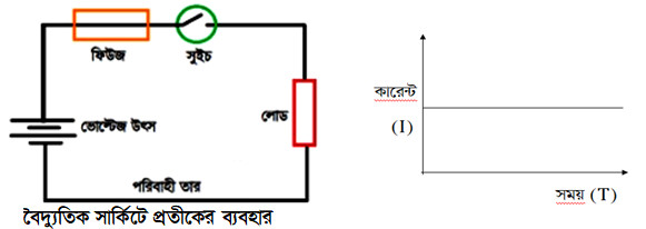
“Alternating Current: The current, specifically, which changes direction while flowing, is called alternating current.” The output polarity of the power source changes with time

Direct Current: Current which always flows in one direction is called direct current. “Since the positive and negative polarities of the voltage source are unchanged, consequently, the direction of the current does not change.”
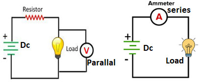
Connection of ammeter and voltmeter in an electric circuit Fig: The voltmeter is connected in parallel with the part of the circuit where the voltage is to be measured. Again the ammeter has to be connected in series with the part of the circuit where the current is to be measured.
Resistance of Conductor: Resistance is a special form of conductor. The part of a conductor that impedes the flow of electricity through it is called resistance. Every substance has more or less resistance. It is expressed by R, the unit of which is Ohm.
Types of Resistance:
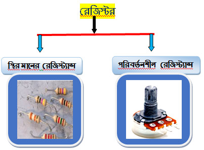
Ohm’s Law: The current flowing through a conductor at a given temperature is proportional to the potential difference across the conductor and proportional or inversely proportional to the resistance.
Mathematical interpretation of Ohm’s law:
Think that,
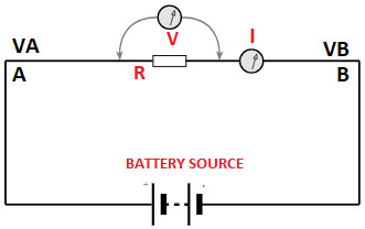
The potentials across the two ends of the conductor AB are VA and VB respectively
The resistance of the conductor is R and the current flowing through it is I.
Potential difference across the conductor = VA – VB = V [Take]
According to Ohm’s law,
I∞ V………….1no [when R is constant]
and I∞ 1/R………2no [when V is constant]
“1no and 2no we get; specifically, I∞ V/R, particularly when both V and R are variable.”
Or, I=K.V/R……….3no [where K is a constant]
Now if the value of K is 1 we get from equation 3no,
I=V/R
This is the mathematical interpretation of Ohm’s law.
Relationship between current, voltage and resistance:
“If the potential difference across a conductor is V, the resistance of the conductor is R, and the current flowing through it is I, then, consequently, the relationship between V, I, and R, according to Ohm’s law, is – “

Mathematical Problems and Solutions:
What current will flow through a 60 watt lamp of resistance 807 ohm , if the lamp is connected to a 220 volt supply.
Solution:
Given, P= 60 watts,
V=220V,
R= 807 ohms,
I= ?
We know, flowing current, I= V/R
=220/807
= . 272 amperes (Ans.)
